
Update 2 - I was featured in engadget.com and hackaday.com
My xmas-box project consists of an internet controlled Christmas lights and music show. A Christmas song can be requested on-line which is then put in a queue and played in the order it was requested. The music is transmitted on an FM station within a 300 ft radius from my house.
The xmas-box has 8 Channels (power outlets) where different light modes can be played: vu meter style, ascending, descending, split, merge, sequence and random. During each song one of these modes is used randomly every 10 seconds (to make the show less monotonous).
I started my research right after Halloween and I came across a couple different options, but I settled with the following combination of hardware : arduino + adafruit wave shield + ioBridge + wifi bridge + solid state relays (SSRs).
The xmas-box is enclosed in a small plastic tool box. I have place it on my deck under a roof ( it is not completely weather proof). The tool box has "3 levels." The bottom is where all the SSRs and AC wiring are located. The middle (the inside tray) contains the wall warts for the arduino (9v), ioBridge (5v) and Wifi Bridge with power. The top level contains the Arduino board, the ioBridge module and the FM transmitter.
 This is the first time I lit my house so I was just able to put 3,300 mini lights, 3 spotlights,1 LED Rope, 4 LED (40 led each) branch trees and 1 reindeer. I hope the lights last so I can keep adding each year.
BoM - Bill of Materials
Here is the list of materials I used for the xmas-box:
- Arduino Duemilanove
Adafruit Wave Shield for Arduino Kit - v1.1 - ioBridge IO-204 Monitor & Control Module
-
- SD card (up to 1 GB)
- PPA Digital FM Transmitter
- 10 K resistor
- 2N2222 transistor
- Linksys WET11 Wireless Bridge
- 8 Solid State Relays (I got mine from ebay for $5 each!)
- 2 PowerSquid Power Multiplier
- Plastic Tool Box
- Electric Cable
- Wire Connectors
- At least 8 sets of Christmas lights (mini lights, C7, C9, or LED sets)


WARNING
You will be dealing with AC power. If you don't feel comfortable or you are not sure how to handle AC, please consult a licensed electrician before starting to wire the relays.
A great advantage of using SSRs instead of mechanical relays is that I did not have to add any diodes, transistors, or resistors. Also since there there is no mechanical dependency the switching will be smoother. I would advise to use a breadboard with 1k resistors and different color LEDs during your prototyping. Then when you are ready you can use the SSRs and real Christmas lights.
The connections are pretty straight forward. I daisy chained the ground coming from the Arduino to each of the 8 SSRs. Then 8 digital outputs from the Arduino were connected to each positive of the 8 SSRs.
I gutted the PowerSquid Power Multiplier and removed the 10 outgoing outlets (5 per PowerSquid) as well as the AC plugs. The 5 outgoing outlets came nicely attached together so I cut one from each that used to power the arduino, ioBridge and Wifi bridge.
I connected all the Neutrals (white) together, all the Grounds (green) and then I took the Live (black) and daisy chained to each of the 8 SSRs. Then I individually wired each SSR Live wires to one of the 8 outlets.
I decided to have two power plugs to make the wiring a bit nicer and less bulky. So basically the SSRs on the left are connected to one wall outlet and the SSRs on the right to the other.

You can download the Arduino Sketch from the bottom of this page (xmas_box.pde).
You will need the following Arduino Libraries:
- AF_Wave and Wave
- String (formerly TextString)
Here is a run down for the pin connections on the Arduino with WAVE shield on top.
Communication
D0(RX) -> ioBridge Serial Board TX
D1(TX )-> ioBridge Serial Board RX
D2-D5 are used by the WAVE shield (they could be changed)
D2 -> LCS
D3 -> CLK
D4 -> DI
D5 -> LAT
xmas-box first 3 channels
D6 -> Channel 1
D7 -> Channel 2
D8 -> Channel 3
FM transmitter ON/OFF
D9 -> 10k resistor -> 2N2222 Base -- Collector and Emitter to FM transmitter switch
WAVE shield
D10 -> LCS
SD card WAVE shield communication (cannot be changed)
D11
D12
D13
Power
Gnd[0] -> Relay daisy chain.
5v pin -> FM transmitter positive
Gnd[1] -> FM transmitter ground
Gnd[2] -> ioBridge Smart Serial Board
Vu Meter
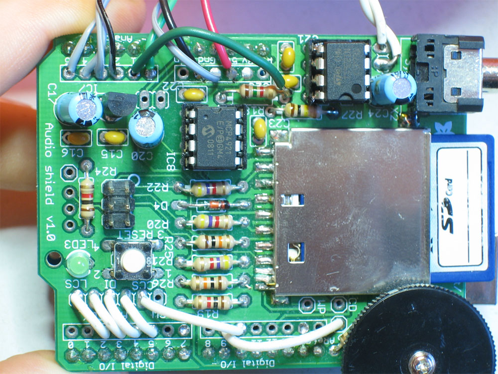
A0 -> R7 1.5K on the WAVE shield to measure output from amplifier. See image.
Analog pins 1-5 are used as digital out for xmas-box channels
A1 = D15 -> Channel 4
A2 = D16 -> Channel 5
A3 = D17 -> Channel 6
A4 = D18 -> Channel 7
A5 = D19 -> Channel 8
Wave shield speaker (mono) to FM transmitter input
You will need the following Arduino Libraries:
- AF_Wave and Wave
- String (formerly TextString)
Here is a run down for the pin connections on the Arduino with WAVE shield on top.
Communication
D0(RX) -> ioBridge Serial Board TX
D1(TX )-> ioBridge Serial Board RX
D2-D5 are used by the WAVE shield (they could be changed)
D2 -> LCS
D3 -> CLK
D4 -> DI
D5 -> LAT
xmas-box first 3 channels
D6 -> Channel 1
D7 -> Channel 2
D8 -> Channel 3
FM transmitter ON/OFF
D9 -> 10k resistor -> 2N2222 Base -- Collector and Emitter to FM transmitter switch
WAVE shield
D10 -> LCS
SD card WAVE shield communication (cannot be changed)
D11
D12
D13
Power
Gnd[0] -> Relay daisy chain.
5v pin -> FM transmitter positive
Gnd[1] -> FM transmitter ground
Gnd[2] -> ioBridge Smart Serial Board
Vu Meter
A0 -> R7 1.5K on the WAVE shield to measure output from amplifier. See image.
Analog pins 1-5 are used as digital out for xmas-box channels
A1 = D15 -> Channel 4
A2 = D16 -> Channel 5
A3 = D17 -> Channel 6
A4 = D18 -> Channel 7
A5 = D19 -> Channel 8
Wave shield speaker (mono) to FM transmitter input

The ioBridge configuration is a breeze! All you have to do is Serial.print the current track number being played to the ioBridge Serial Board. The serial board will hold the track number and have it available to be retrieved by the Data Feed API in JSON format (LastSerialOutput).
I also created a series of widgets with predefined xmas-box commands for a one-click input.
Here is the syntax to communicate with the xmas-box through serial communication. The semi-colon indicates the end of the command.
Next track
n;
Put on queue
q(1-99);
Put on queue with specific light mode
q(1-99)m(1-8);
Change light mode
xxxm(1-7);
Turn all lights on/off
xxxm8{1/0);
Turn individual channel on/off
xxxm9(1-8)(1/0);

I was hoping to find a Belkin TuneCast II since I have found a lot of information online (including this instructable ) but I had to settle with the PPA Digital FM Transmitter and it worked out pretty well! The only modifications I had to do were to desolder the stereo mini plug and connect 2 wires coming from the WAVE shield speaker output and desolder the mini barrel plug to connect power directly from the Arduino.
I'm powering the FM transmitter with the 5v coming out from the Arduino. This would probably not be a good idea if I was powering the Arduino with a 9v battery but since I'm using a wall wart I'm not too concerned.
I am bypassing the ON/OFF switch by connecting a 2N2222 transistor connected to a 10k resistor coming from a digital output from the Arduino. To turn on I just send a fast HIGH/delay/LOW and that's all I need to start the FM transmitter.
I also soldered a wire as an antenna to the ground of the battery power pin.
 Web Interface
I decided to leave the job of song queuing to a web application. I am using Oracle Application Express (APEX) for http://xmas-box.com since this is my favorite rapid web application development tool. But this can also be managed by any database oriented web solution (ie Linux/Apache/MySQL/PHP - LAMP).
I have 2 main tables:
SONGS - It stores the name and artist of the song
QUEUE - it stores the song requests
The web app uses jQuery to retrieve the ioBridge JSON Data Feeed API to determine the current song being played. Using Javascript I retrieve LastSerialOutput node that holds the number of the current track.
Then another jQuery calls my web application REST service and sends the track number. The REST service returns the song name,artists and name of the person that requested the song.
If the song was not on the queue it means that its just looping through the play list. So in this case the requester will be Santa Claus itself! And it will show Santa's current location by retrieving it from http://www.noradsanta.org/ feed.
The page might have a live view and live sound, but I'm still working on that...
I'm powering the FM transmitter with the 5v coming out from the Arduino. This would probably not be a good idea if I was powering the Arduino with a 9v battery but since I'm using a wall wart I'm not too concerned.
I am bypassing the ON/OFF switch by connecting a 2N2222 transistor connected to a 10k resistor coming from a digital output from the Arduino. To turn on I just send a fast HIGH/delay/LOW and that's all I need to start the FM transmitter.
I also soldered a wire as an antenna to the ground of the battery power pin.

I decided to leave the job of song queuing to a web application. I am using Oracle Application Express (APEX) for http://xmas-box.com since this is my favorite rapid web application development tool. But this can also be managed by any database oriented web solution (ie Linux/Apache/MySQL/PHP - LAMP).
I have 2 main tables:
SONGS - It stores the name and artist of the song
QUEUE - it stores the song requests
The web app uses jQuery to retrieve the ioBridge JSON Data Feeed API to determine the current song being played. Using Javascript I retrieve LastSerialOutput node that holds the number of the current track.
Then another jQuery calls my web application REST service and sends the track number. The REST service returns the song name,artists and name of the person that requested the song.
If the song was not on the queue it means that its just looping through the play list. So in this case the requester will be Santa Claus itself! And it will show Santa's current location by retrieving it from http://www.noradsanta.org/ feed.
The page might have a live view and live sound, but I'm still working on that...

During my research I stumbled upon a few mentionable resources. My requirements became more tight since I wanted a computer-free solution, a stand-alone application and that is why I went with the WAVE shield . Another possible way is to get a cheap mp3 player and build an op amp low filter to detect beats on the music, but then again the WAVE shield is actually pretty inexpensive so it worked out better.
Beat detection
One of the easiest ways to do an Arduino based light/sound show is by using a combination of Proccessing + Minim+ Firmata. All you need is to have serial communication from your pc to your arduino. These instructables rely on Minim's beat detection and could be adapted for Christmas lights:
LED Dance Room
Music Synchronized LED Pumpkin
Relay board fabrication
You can follow the Arduino Christmas Light Controller Instructable if you prefer to build your own relay board. Note that this will be using mechanical relays instead of SSRs.
Internet communication
Another alternative for the web control part is to have a secondary Arduino with a Ethernet shield or a wi-fi shield (it will be absolutely necessary to have a second Arduino board). But as a side note I really like using the ioBridge module. Their servers manage all incoming/outgoing connections and the Data Feeds and APIs offers great flexibility.
Commercial/Hobby products
diylightanimation.com (Linx)
animatedlighting.com (they got a Christmas In A Box 4 channel for $500!!)
Ligh-O-Rama


